UltraCEM™
Continuous Emissions Monitoring System
Outdoor All Weather Version
Key features
- One (1) to Five (5) channel multi gas measurement capability
- Time proven high Accuracy/Sensitivity gas detectors utilize:
Paramagnetic (O2), IR (CO & CO2), Chemiluminescent (NOx) , UV or IR (SO2), FID (THC) - All Weather NEMA 4X Box construction designed for Outdoor monitoring
- Environmentally controlled Shelter not required
- Independent Analysis and Sample conditioning
enclosures allow for Ultra Versatile Installation Options:- Mount at Stack Port for minimum installation costs/Heated Sample Line not required.
- Mount at the bottom of the stack utilizing a stack sample probe and Heated Sample Line
- Mount the SCU on the stack port and the MAS in a control room to allow for easy operator maintenance and low installation costs.
- Easy to Service Front Access Components
- All Computer parts are industry Format PC for easy
upgrades or replacements - Optional Laptop PC with wireless transmission
- HTML “web-browser” operator interface provides user display and interface from anywhere in the world via the world wide web
- Digital Mass Flow Controller precisely controls gas sample flow leading to the highest accuracy
- Industry standard robust sample conditioning components
- Optional Hazardous area Div. I & II options
PRODUCT DESCRIPTION
The Cemtrol UltraCEM system is a Field Mount Continuous Emissions Monitoring System that uses proven extractive monitoring technology, is coupled with state of the art measurement detectors and utilizes a semiconductor industry standard PC electronics platform for maximum measurement, communications and processing capabilities.
The UltraCEM is designed to extract a sample gas, condition the sample, analyze for the desired constituents, and process the emission data by utilizing the required calibration validation calculations/procedures and O2 diluent corrections as stipulated in 40 CFR Part 60/75 regulations. The UltraCEM system is also a Data Acquisition System that will store relevant raw/diluent corrected emissions, flags, calibrations and alarms for a period of 3 months.
1.0 The UltraCEM system consists of two major components:
- Sample Conditioning Unit (SCU)
- Measurement Analysis System (MAS)
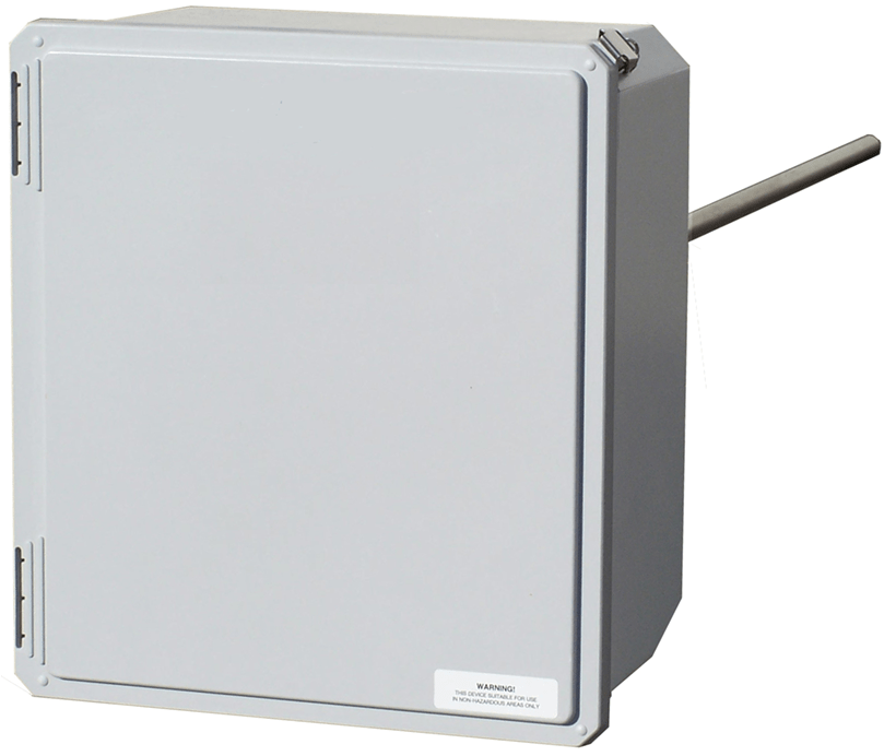
1.1 Sample Conditioning Unit (SCU)
The sample gas is extracted by a specially designed probe and is then conditioned by utilizing the UltraCEM sample conditioning/Probe Box. The box can be located at the sampling location or remote and consists of the following equipment:
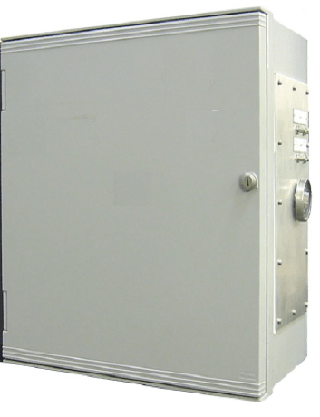
1.1.1 Housing
This enclosure is rated NEMA 4X (Optional Explosion Proof) and can be mounted directly in the outside environment. Sun and rain shields are recommended in certain environments to maintain proper performance specifications. The temperature controlled housing is
completely piped and wired and is accessible to the
customer via bulkhead and terminal block termination
points. All sample lines, fittings and valving are stainless
steel, Teflon and Polypropylene. The housing is
equipped with a strong 2500 btu Vortex Air Cooler along with a strip heater that is equipped with a thermostat that precisely maintains the required internal enclosure temperature.
1.1.2 Cleaning
The gas sample is cleaned with three levels of filtration: Primary filtration is performed at the probe tip by utilizing a 2 micron filter. Secondary filtration occurs after the sample pump via a coalescing filter/dryer. The MAS incorporates an additional 0.5 micron paper filter.
1.1.3 Sample Drying
The UltraCEM provides a dry basis gas measurement. The UltraCEM dries the sample gas by utilizing a dual pass thermo electric chiller. The chiller cools the sample to a temperature of 4 degrees Celsius +/- 1C. As the temperature of the sample gas decreases below the moisture dew point, condensation is removed. The moisture is then drained continuously by a peristaltic pump while the dry sample gas is allowed to continue through the system. The gas sample is then passed through a membrane-type high efficiency permeation dryer that will dry the sample to a – 40 degrees Celsius dew point. This intensive drying process allows for extreme analytical accuracy and eliminates inaccuracies due to corrosion issues.
1.1.4 Sample Pump
The pump is a positive displacement type pump that uses a moving diaphragm. All wetted parts are 316 SS and or Teflon depending upon the application. In normal operation the pressure at the pump outlet is set between 10 – 15 psi.
1.1.5 Vents and Drains
All vented gases or drained fluids are vented through bulkhead unions. Customer may route them to a sump. If the housing is located in a well-ventilated area, the gases can be vented to the atmosphere, otherwise they should be vented out of the room
1.1.6 Wiring
All termination points for incoming or outgoing signals are provided via terminal strips or plugs.
1.1.7 Sample Probe
A specially designed probe extracts sample gas from the stack. The probe is constructed of 316 Stainless Steel. The probe tip is fitted with a sintered filter and the filter can be easily changed and serviced. Calibration fittings are provided so that the system complies with EPA guidelines for auto calibration as outlined in US EPA 40 CFR Part 60/75 regulations. Cemtrol provides a solenoid-operated valve for auto blowback of probe. Customer must provide the instrument air supply.
1.1.7.1 The sample probe
has optional 4“ and 6“ flange adaptors available and is available in a variety of probe lengths.
1.1.8 Optional External Sample Probe
As an installation option the UltraCEM can be fitted with an External Probe to accommodate the user’s exact installation requirement. The use of the External Sample Probe will allow the user to locate the SCU either at the base of the stack where it can be easily maintained or in a temperature controlled room. Note that Heated Sample Line is required when using the optional external probe. The external probe design utilizes the following:
- Heated out of stack Ceramic 2 um filter element – 3” or 9” length dependent upon the application
- 2” ANSI mating flange
- Sub-flange for easy removal of filter chamber
- Integrated thermo-switch with SSR for control of filter chamber to 375o F
- 60” Probe Tube for insertion into stack.
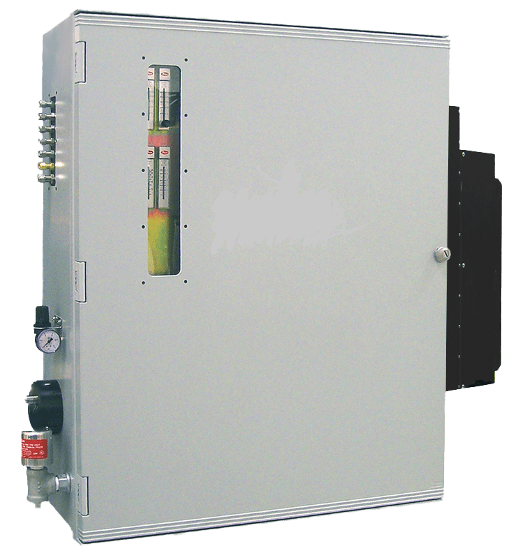
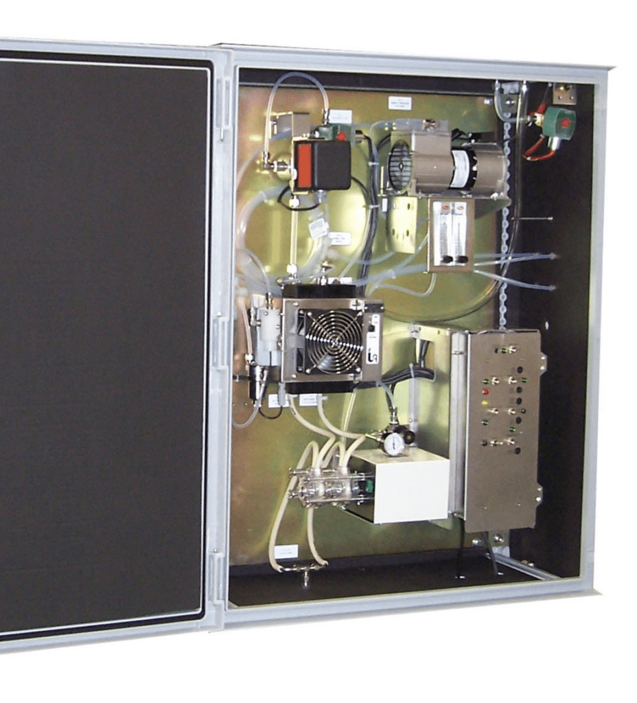
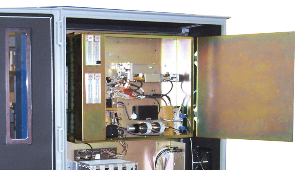
1.2 Measurement Analysis System
The UltraCEM design includes an Analysis box which accommodates all of the measurement detectors and computer components. The box can be located at the sampling location or up to 500’ away from the sample handling box for user installation flexibility. This enclosure is rated NEMA 4X (Optional Explosion Proof) and can be mounted directly in the outside environment. Sun and rain shields are recommended to maintain proper performance specifications.
1.2.1 O2 Detector (Paramagnetic)
The determination of oxygen is based on the
measurement of the magnetic susceptibility of the
sample gas. Oxygen is strongly paramagnetic, while other common gases are not. The detector used is compact, has fast response and a wide dynamic range. The long life cell is corrosion resistant and may be easily cleaned. It has rugged self-tensioning suspension and is of welded Non-Glued construction. Standard range is 0-25%.
1.2.2 CO & CO2 Detectors (IR)
The non-dispersive infrared method (single beam double wave) is based on the principle of absorption of infrared radiation by the sample gas being measured. The gas specific wavelengths of the absorption bands characterize the type of gas while the strength of the absorption gives a measure of the concentration of the gas component being measured.
A pair of gas filled cuvettes are mounted on a rotating disc. The reference cuvette is filled with a sample of the gas to be measured and the measure cuvette with nitrogen. This technique is known as gas filter correlation. They pass through the beam of light alternately. The difference in absorbance is measured by the detector and provides a direct output of the gas concentration. Standard dual range capability between 10 – 100% adjustable by user.
1.2.3 NOx (Chemiluninescent)
The NOx detector consists of an ozone generator, chemiluminescence reaction chamber and a photomultiplier tube detector. The reaction chamber operates at atmospheric pressure. This eliminates the bulky vacuum pump found in other chemiluminescent instruments. The reaction between Ozone and Nitric Oxide is used to determine the presence of Oxides of Nitrogen (NOx) in a sample gas. Nitric Oxide and Ozone readily react to form nitrogen dioxide in an electrically excited state. The excited NO2 immediately reverts to the ground state, emitting photons. The light intensity is measured by the peltier controlled photomultiplier tube detector. Standard dual range capability between 5 – 1000ppm is adjustable by user.
1.2.4 SO2 Detector (UV or IR)
The absorption measurement in the SO2 spectral range is based on the same principle as the IR measurement. The standard range capability is between 25 to 2000ppm and is adjustable by user.
1.2.5 Automatic Calibration
To minimize the effect of long term zero and span drift in each analyzer detector, the PC system controller periodically initiates a calibration cycle as specified by the user. This feature assures reliable, accurate data while minimizing the attention required by operating personnel.
At adjustable intervals, the microprocessor will energize the appropriate valves which cause first zero, mid and then span gas to flow through each analyzer. When the analyzer readings stabilize, the PC Controller calculates the zero and span drift value for each detector. If a significant measurement deviation from the standard gas value exists, an alarm is generated which must be reset.
1.2.6 System Controller/Data Acquisition System
The PC controller is a standard off the shelf PC based platform and will perform all hardware control, as well as provide select data processing capability for the UltraCEM-P. Both analog and digital inputs and outputs are provided, including data correction and average values. Some capabilities are:
- All automatic and manual functions.
- Automatically calibrates each gas analyzer at selected time intervals to ensure accuracy
and regulatory compliance. - Automatically controls back-purge of sample probe with instrument air.
- System limit and failure alarms.
- I/O digital and analog signal interfaces.
- Applies calibration correction factor for each analyzer output, data averaging for
regulatory requirements (3 months data storage of 15 minute & 1 hour averages, 1 week storage of 1 minute averages) - Applies O2 diluent correction and stores data as separate value.
- Standard Ethernet port for HTTP Web browser viewing/internet Data Download capability.
Access the menu and data from anywhere in the world from any PC via the internet. - RS232, RS485 or Ethernet links utilizing state of the art TCPIP communications
capabilities. - Latest processor with Printer Port, Keypad Port and Monitor Port.
- Single button initiate to download data into excel format. Simple regulatory reports can
then be tailored by the user.
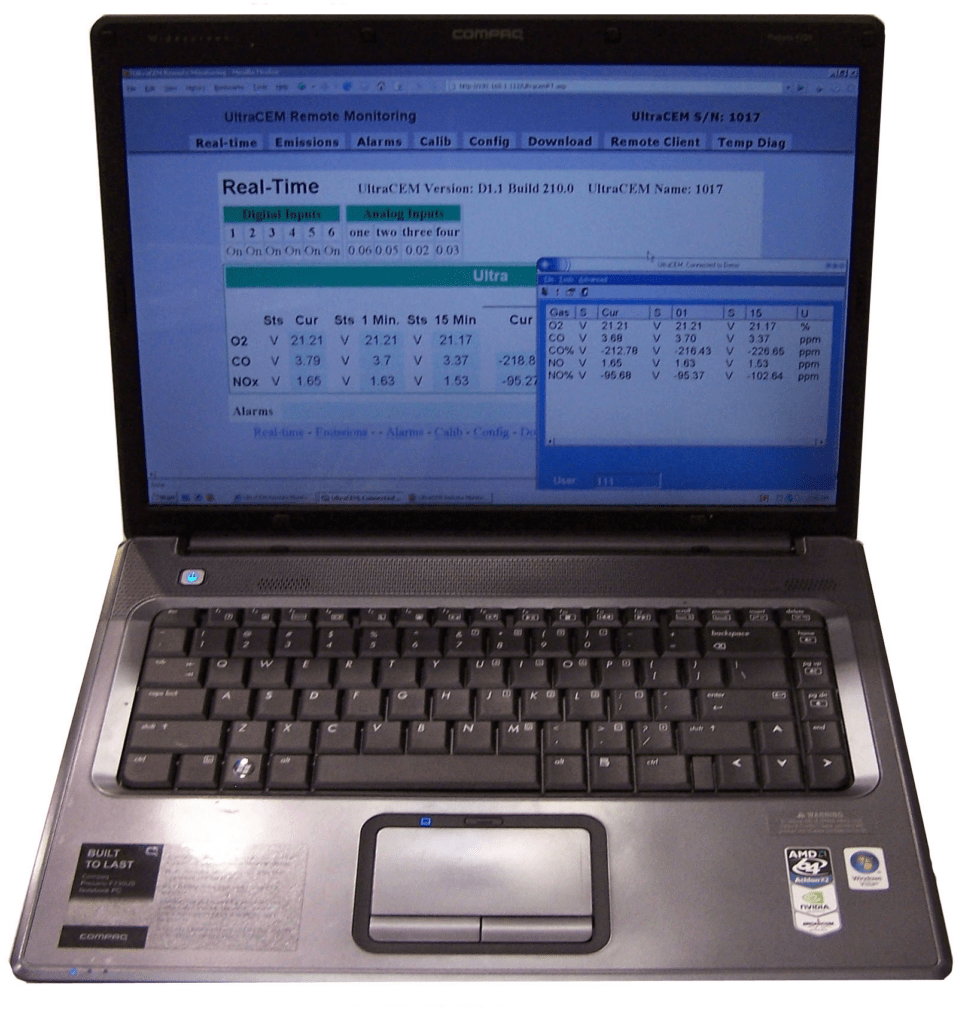
1.2.7 User Interface Software & Communications
User Interface with the UltraCEM is performed with a PC or Laptop with either an Ethernet Cable Connection or via a Secure Wireless 802.11g WiFi Communication. The UltraCEM utilizes a very easy to use menu structure, Field Friendly Interface (FFI), allowing the user to easily scroll through menus, view, edit and print data via standard Microsoft tools.
An Optional Laptop PC, configured for Wireless connection to the UltraCEM MAS, is available.
1.2.8 Sample and Calibration Gas Distribution
- The gas and calibration gas samples are controlled by a single Digital Mass Flow Controller (MFC). The MFC controls the sample gas and calibration gas sample gas flow very accurately. The use of an MFC allows for very high accuracy and reliable monitoring.
- The MAS Panel is equipped with a 3 way universal solenoid that will accommodate the gas sample for either the normal stack gas or direct the calibration gases directly to the analyzers otherwise known as a local calibration.
- The UltraCEM is equipped with a manifold with qty. 4 two way Normally Closed solenoid valves that will direct the customer supplied calibration gases into the system. The three valves will be used for Zero, Mid and Span1 & Span2 gas calibrations respectively.
- The panel is equipped with a gas vent line. The vent will be routed to a sump by customer. If the housing is located in a well ventilated area, the gases can be vented to the atmosphere. Otherwise they should be piped out of the room or building.
- The Chemiluminescent detector requires a continuous source of instrument air from customer. The enclosure is equipped with a bulkhead fitting for this connection.
1.2.9 Accurate Detector Temperature Control Box
All measurement detectors are located in a compartment design equipped with a highly efficient environmentally sealed electric heater controlled system. The detector enclosure is kept at a constant temperature (42 degrees C +/- .1) enabling the analyzer to produce extremely accurate measurement results due to the fact that the temperature control is stable and at ideal temperature.
SPECIFICATIONS – Measurement Analysis System (MAS): GENERAL
Power: Universal Power Supply 85 – 125 VAC, 50 – 60 Hz, + 10%, 500 Watts Maximum at Start Up. 250 Watts Nominal
Detectors//Number: NDIR (CO&CO2), UV or IR (SO2), Paramagnetic (O2), Chemiluminscent (NOx). Up to five in one analyzer
Mounting: Wall Mount
Area Classification: General Purpose or Optional Hazardous Area CSA (Pending)
Compliance’s: CSA (Pending)
Ambient Temperature Range: -400 to 500 Celsius.
Relative Humidity: 99%
Inputs/Outputs:
Data: RS-485 Serial Port. (Multi-Drop Network)
- RS-232 Serial
- Port.
- LAN, Ethernet 10/100-BaseT
Connectivity Protocols: HTML (Web Browser) – Status, file transfer Modem / Web browser
- TCP/IP, MTTP ASCII String
- Microsoft Shared drive
- FTP Logs download
- TELNET Server
Analog Outputs: Qty. 8 Isolated 4-20 mA dc, 500 ohms Max Load (O2, CO, CO2, SO2, NOx, THC and 3 spares)
Analog Inputs: Qty 4 (Typically; Stack Flow, Opacity, MW, Fuel Flow) Digital
Digital Outputs: Qty. 10 dry contact digital Outputs; maximum 110VAC @ 1 amp load. Typical; O2, CO, CO2, SO2,THC, and NOx limit exceed, data valid, in calibration, in maintenance, trouble alarm
Digital Inputs: Qty. 10: (Typical Process on/off, Flame Detect, Shutdown or Initiate Cal, flow signals and Opacity signals). Interrogated with 5 VDC.
Instrument Weight: 80 lbs. Typical
Size: 40“ X 30“ X 12“ (H W D)
Ambient Temperature Range: -400 to 500 Celsius.
Relative Humidity: 99%
Ranges: O2: 0 –1 Selectable to 0 –25% (1% increments)
CO: 0 –10ppm Selectable to 100% (1ppm increments)
CO2: 0 – 5 ppm Selectable to 100% (1ppm/% increments)
NOx: 0 – 5 ppm Selectable to 10,000ppm (1ppm increments)
SO2: 0 – 25ppm Selectable to 2000ppm (1ppm increments)
THC: 0 – 5 ppm Selectable to percent levels
Sample flow rate: 1000 to 3000cc/min Warm Up Time: Max 30 minutes
Warm Up Time: Max 30 minutes
SPECIFICATIONS –Sample Conditioning Unit (SCU): GENERAL
Power: Universal Power Supply 85 – 125 VAC, 50 – 60 Hz, + 10% 500 Watts Maximum at Start Up. 250 Watts Nominal
Mounting: Wall Mount
Area Classification: General Purpose
Compliance’s: CSA (Pending)
Ambient Range Temperature: -400 to 500 Celsius (Colder & Hotter options available)
Instrument Weight: 70 lbs Typical
Size: 40“ X 30“ X 12“ (H W D)
Stack Sample Moisture: Typical 50%
Sample Cooler: Thermo Electric type with dual pass Chiller in conjunction with Permeation Tube in Series.
Max. Stack Temperature: Standard 14000 F (Higher upon Request)
Stack Pressure: Typical -5 to 15 inches H2O
Sample Flow Rate: 1000 to 3000cc/min
Response Time: 30 seconds/100′ of Line (1/4″ tubing)
Probe Length: 48″ length 316 SS Probe with 0.5 micron sintered filter. Optional 5’ and 6’ probes.
Mounting Flange: Standard 4“ 150# Raised Face (2 Hole Top). Shipped Equipped with Gasket
Optional External Probe
Mounting Flange: Standard 4“ 150# Raised Face (2 Hole Top). Shipped Equipped with Gasket
Sample Pump: 316 SS or Teflon diaphragm type
Instrument Air Requirements: Instrument grade air required. Max 25 SCFM @ 90 PSIG @ 500 C Ambient.
Paramagnetic O2 ) | NDUV SO2 FID THC | NDIR CO/CO2 | Chemiluminescent NOx | |
Linearity | <+/- 1% | < +/- 1% | < +/- 1% | < +/- 1% (1) |
Zero Drift | < +/- 1% /day | < +/- 1% /day | < +/- 1% /day | < +/- 1% /day (1) |
Span Drift | < +/- 1% /day | < +/- 1% /day | < +/- 1% /day | < +/- 1% /day (1) |
Repeatability | < +/- 1% | < +/- 1% | < +/- 1% | < +/- 1%/day (1) |
Response Time (t90) | 10< +/-t90< +/-15 | 30< +/-t90< +/-45s | 15s< +/-t90< +/-30s | 20s< +/-t90< +/-30s |
Influence of Ambient Temperature (-40C to 50C) –On Zero -On Span | < +/-1% < +/-1% | < +/-2% < +/-2% | < +/-2% < +/-2% | < +/-2% < +/-2% |
(1) 0-10ppm NOx range is <+/- 2%.
2.0 Equipment to be supplied by others
- 2.1 Calibration gas bottles
- 2.2 Calibration gas regulators. Dual stage with CGA connector
- 2.3 Instrument Air supply
- 2.4 85-125 VAC, 50-60Hz plant power supply
- 2.4.1 SS or Teflon 1⁄4” Tubing between MAS & SCU
- 2.4.2 Wiring trays for electrical interconnection wiring
- 2.4.3 Sample ports for probe connection & mounting hardware
- 2.4.4 Heated Sample Line between Probe & SCU for Optional External Sample Probe Version
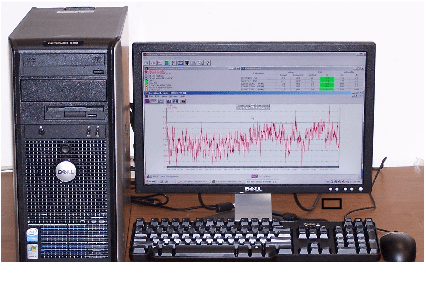
Optional Data Acquisition System & Reporting EPA 40 CFR Part 60 thru 75 Regulations
- The DAS displays all pollutant concentrations, calculated emission values, required emission averages, alarm conditions calibration results and CEM status.
- Automatic and on-demand generation of all required reports. Reports may include daily, monthly and quarterly summary reports, exceedance reports, downtime reports and calibration reports.
- An event and alarm log that records all alarms, system problems and operator modifications.
- Operator-assignable reason codes for incorporation in exceedance reports.
- Five Year Data Storage in DAS Computer.